Why Not to Specify the Density of Thermal and Acoustic Duct Insulation Used in HVAC Ductwork
Courtesy of SMACNA National | smacna.org
In sheet metal ducts, insulation is often an important component of the system. Fiberglass and closed cell foam insulations are commonly used for thermal insulation to reduce heat transfer, or acoustic insulation is used to reduce noise levels.
When used to reduce heat transfer, insulation can be saving energy and/or be preventing condensation. As a noise reduction medium, it can reduce the noise levels inside ductwork caused by the fan, generated from duct or components, or caused by noise breaking into the duct system from its surroundings. When specifying insulation, the design engineers should specify the performance parameters of importance, depending on if the insulation is for thermal control, noise reduction, or both.
Thermal Control
Insulation is applied to ductwork to increase thermal resistance, reduce energy loss, and prevent condensation or dripping from the duct. Thermal insulation is often needed because air transported through a supply duct is at a temperature different from that of the surrounding space where the duct is located. For example, the air inside the duct may be at 55°F while the temperature surrounding the duct could be between 70°F to 90°F or more in the space above the room, since ductwork most often runs through unconditioned spaces. Insulation reduces the rate of thermal loss or gain from those surroundings. The air may need extra heating or cooling to arrive at the design supply air temperature if the supply duct is uninsulated.
Insulation helps to prevent condensation and dripping from air-conditioned ducts, which very often transport air at temperatures below the external local dew point. In the absence of insulation and vapor barrier, water will condense and could cause corrosion and other damage.
R-Value
The thermal resistance of insulation is determined by its R-value, which is the resistance measured at a known temperature difference between the air inside the duct and air outside the duct. R-value accounts for all the heat transfer modes that take place in the air conduction systems. It depends on the insulation material, its thickness, and its density. For example, the thicker the material, the higher is its thermal resistance. However, while the thermal resistance of the insulating material is known, the overall thermal resistance between the air in the duct and the surrounding space also includes the internal and external film resistances, leading to a larger resistance than just the insulation resistance by itself.
Building codes specify the amount of insulation required for ducts in terms of resistance. For example, ASHRAE 90.1 and California Title 24 specify the minimum insulation R-value for supply and return ducts, considering both heating and cooling ducts. It could be up to an R-8.
Thermal Conductivity: k
Laboratory tests are used to determine the thermal conductivity of an insulation. It basically represents how fast the heat is transferred at a given temperature difference. The R-value for just the insulation is calculated from:
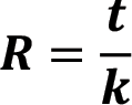
where t is the thickness of the insulation in inches and k is the thermal conductivity of the insulation in units of Btu•in/(hr•ft2•°F). The relationship shows that the higher the thermal conductivity of an insulation material, the thicker it has to be to deliver the same thermal resistance.
Values of thermal conductivity are determined experimentally at a mean temperature of 75°F and typically range from 0.23 to 0.35 Btu•in/(hr•ft2•°F) in duct insulations. So for t = 1 inch, and k = 0.25
Btu•in/(hr•ft2•°F), the resistance R is:

The units are normally left off for R-values and the one for this would be an R-4.
The resistance equation can be rewritten to calculate the thickness required for a specified thermal conductivity:

Using the same units, if an R-8 is required and the thermal conductivity is k = 0.25 Btu•in/(hr•ft2•°F), then

So, the density is not what should be specified to meet an R-value; the thermal conductivity should be specified. Given the thermal conductivity the manufacturer or installing contractor will need to determine thickness needed to meet the R-value.
The thermal resistance of an insulation is a function of the insulation type, its thickness, and its composition. For example, the thermal conductivity of mineral wool is higher than that of fiberglass for the same density. A typical mistake in specifications is to specify the associated density or a thickness of the insulation, rather than the R-value or the thermal conductivity, k, and the thickness. Materials may have different densities, but they may have a similar thermal performance. Specifying an R-value can give the contractor options. They may be able to use a thinner material with a low thermal conductivity or may have to use a thicker insulation thickness to meet the R-value.
Acoustic (Noise) Control
Noise control is often the main reason to specify an insulation. Sound starts at a source that causes the air or material to also vibrate and create sound waves. Sound waves propagate in all directions. In an HVAC system sound propagates from the source (fan) to a receiver through many different paths as depicted in this figure:
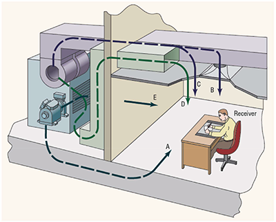
Although there are many different sounds that a receiver (the human) may hear, usually the loudest sound is from the fan. Air movement through ducts also generates noise that travels down the sound path in the ductwork. The ductwork, both supply and return, is generally the main path for the sound (although, as you can see, there are other paths). Metal ducts are very good transmitters of sound. Without proper attenuation, these sounds can be unacceptable at the receiver.
Noise can be controlled at the source (use a quieter fan or sound enclosure), controlled along its path (use of insulation), or controlled at the receiver (ear plugs, masking). This paper focuses on using insulation to control noise levels.
Insertion Loss, Noise Control in Ducts
Sound has two major characteristics: loudness, measured in decibels; and pitch, measured as frequency or cycles per second. One might choose to use duct insulation, silencers or a combination of the two to control the noise level. Each will have data on the sound attenuation (insertion loss) as a function of the frequency band where the noise is occurring. The designer should choose the method of controlling the sound as a function of its loudness and frequencies.
The designer has to determine if the chosen silencer or duct liner has the right insertion loss for the noise spectrum to reduce the sound power level to that needed at the location of the receiver. The industry has already established that density was not a major factor in measuring or determining the insertion loss of lined ductwork. Insertion loss is a function of size, insulation thickness and length. This is evidenced by the regression equations developed to calculate insertion loss of rectangular or round duct which do not include a factor for density. As shown in the SMACNA HVAC Sound and Vibration Manual, First Edition:
For rectangular duct, the insertion loss equation is:
IL = B(P/A)C tD L
Where:
the size factor is perimeter/area, P/A, 1/ft
t is the thickness, inches
L is the length, ft
B, C and D are regression coefficients from Table 5-4 of the SMACNA Manual.
For round duct, the insertion loss equation is similar:
IL = (A + B x d + C x d2 +D x d3 + E x t) x L
Where:
the size factor is the diameter d, in
t is the thickness, in
L is the length, ft
A, B, C, D and E are regression coefficients from Table 5-8 of the SMACNA Manual.
Neither of these equations have a factor for density!
What Designers Should Specify
Insulation density plays a minor role in both thermal and acoustic performances. However, density is not a performance parameter. For thermal control the designer should specify insulation properties that give them the desired result. For example, if the designer wants an R-6 value, then insulation should be specified with the thermal conductivity and thickness that will give them the R-6 value. In this case a thermal conductivity of k= 0.25 Btu•in/(hr•ft2•°F), and 1.5-inch thickness will give R = t/k = 1.5/0.25 = R-6. Or if R-6 is specified, the designer can calculate the thickness that should be specified from t = kR = 0.25 x 6 = 1.5 inch.
For noise control in the duct systems, the designer will need to determine if using a silencer or lined duct should be used. For a silencer, the designer should specify the required insertion loss and maximum pressure drop allowed. Nothing is required for density. The installer would need to match the insertion loss against manufacturer’s data on their silencers. There are often several silencers that will meet the insertion loss and pressure drop specifications.
If the designer chooses duct liner to control the noise, they will need to determine how much liner in feet is required for 1-inch or 2-inch thickness for the duct dimensions given. The density will not be a factor and the designer should just require the duct liner to give the necessary insertion loss. Any manufacturer’s standard insulation should give the necessary insertion loss if the acoustics are designed correctly.
If the insulation is necessary for both thermal and noise control, the designer should specify the insulation to take care of the thermal control necessary as the insertion loss will be about the same regardless of the insulation chosen.
Summary
From a thermal perspective, it is critical to specify thermal conductivity and thickness or R-value to determine the performance of the insulation. Specification of density or thickness alone does not lead to a minimum thermal performance.
Similarly, the acoustic performance is not determined by density or thickness alone; the performance parameter is the insertion loss.
Designer specifications should be performance-based. Leave out the density as a specified requirement. ■